
- Pin Ball Machine
- Brand
- Per Play
- Platform
- Publisher
- Region Code
- Type
- 3d Diy Puzzles Kit (4)
- Area Rug (25)
- Bike Carrier (11)
- Bracelet (5)
- Brooch (7)
- Game Machine (6)
- Handheld System (5)
- Lamp Bulb (7)
- Multi Platform (6)
- Necklace (8)
- Pin (5)
- Pinball Game (5)
- Pinball Machine (5)
- Pinball Machines (1991)
- Regular (6)
- Set (5)
- Single (18)
- Terminal Arcade (5)
- Tow Ball (10)
- Tow Bar (21)
- Other (3168)
Bally / Stern / Alltek Lamp Driver Board TESTER
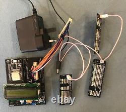
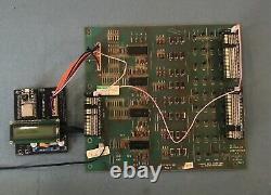
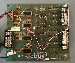
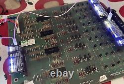
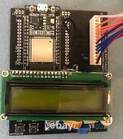
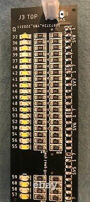
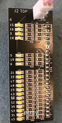
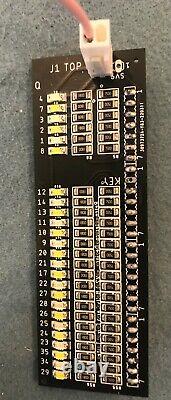

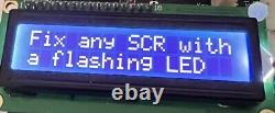


Introducing the Bally / Stern / Alltek Lamp Driver Tester. I got a bit sick and tired of chasing my tail when trying to figure out why controlled lamps in a game were not working, so I designed and built myself a tester. The Bally / Stern Lamp Driver Tester, "LDT" is a quick and easy way to test and diagnose problems with the Bally AS-2518-23 (or AS-2518-14) and Stern LDB-100, Lamp Driver Boards found in many Solid State Pinball Machines from the late 1970's until the mid-1980's. It will also test modern replacement boards such as the Alltek lamp driver board. These boards can control up to 60 feature lights in a game, and have 60 separate circuits, and are prone to common failure. It is often a time-consuming job to locate the correct circuit, needing reference to the game's schematics/circuit diagrams to locate the correct circuit.
The LDT eradicates all this and quickly identified which circuit(s) is at fault, without needing to dig out the schematics. When trying to diagnose a problem in a game whereby one (or more) of the feature lights are not working, there are several possibilities for the cause. Corroded or loose lamp socket. Wiring issue: loose or mis-connected. Blown open circuit SCR's.
Faulty MC14514 Multiplexor IC's - U1, U2, U3, U4. Cracked or non-conducting (dirty) header pins. Disrupted communications between the MPU board and the Lamp Driver Board. Often you can waste a lot of time going round in circles trying to figure out what the issue is. The LDT speeds up and simplifies the process by helping you identify board issues, blown SCR's, faulty U1-U4 IC's, cracked header pins, etc. It also ensures the J4 header connector (the one that connects to the MPU) is working correctly. The LDT will show you which of the 60 circuits are faulty very quickly. It is a nice feeling to know that your lamp driver board has been fully tested, and, where necessary repaired to fully 100% working order. It is then easy to diagnose any remaining non, working lamp issues because you know the board is 1100% working, and so can look at issues 1-4 above. With the LDT, a board can be tested either in-situ, without having to remove from the machine, or can be removed from the game, and tested on the bench.The LDT provides its own power source and also provides power to the Bally or Stern Lamp Driver board that is being tested, so is a complete stand-alone test rig. The LDT is a micro-computer controlled test system, utilizing an ESP32s processor system which sends power and test signals to the Lamp Driver board, and performs a variety of different tests which enable you to quickly identify any faulty components. The main board consists of the ESP32s processor, a power regulator board, an LCD display and some drive components, along with a header connector to connect up to the lamp driver board (J4) and the 3 Led display boards. Each of the Led display boards, connects on to the relevant J1, J2, J3 header on the lamp driver board.
Each board is labelled J1, J2, J3, so it is easy to identify which board should go where. There are two ways to test a lamp driver board whist installed in a game. Using the game's in-built lamp test.
We can use the games in-build lamp test (in the system self-tests), to check if the lamp driver board is fully working. Remove the J1, J2, J3 connectors from the lamp driver board. Install the 3 LED display boards onto their named header pins. Connect up the fly lead to a common controlled lamp point e. On the back of the insert door.
Power up the game and go into self-test, then lamp driver test i. Press the inside coin door self-test button once.
All the leds on the 3 boards should flash on and off. Any locked on, or non lighting leds indicate an issue, note the SCR "Q" number printed on the left hand side of each board next to each Led - this is probably at fault. If any faults are found, remove the board to work on the bench and follow the "Testing - on the bench" procedure below.
Remove the J1, J2, J3, J4 connectors. Install the header connector from the LDT controller to J4 on the lamp driver board. Power up the LDT (but leave the game switched off). Follow the instructions for "Testing - on the bench" below. Testing - on the bench. This is the preferred method of testing, it takes very little effort to remove a lamp driver board from a game, remove two screws and unplug 4 push on connectors. With the board out of the machine and on the bench. Perform the 3 tests: "Lock on", "Auto SCR" and "Single SCR" tests. These are described in detail below. On initial Power the LTD controller will display an opening message on the LCD display, along with a version number. After a second or two this will disappear, and a message asking you to press start for the next test. The first test is the "Lock On" test, Press start to commence the test. The system will apply flashing power to the board, and any faulty circuits that are "Locked on" will show up, as their corresponding LED will flash. For a perfect board, no LEDS should light at this stage.If any Leds flash, note the Q number which is printed on each LED display board to the left of each Led. Locked on issues are normally caused by a faulty SCR which has short circuited, so test or replace the SCR's you have identified by their Q numbers. All SCR's on the board are clearly labelled with their Q number. It is sometimes possible to get a faulty drive chip (these are the MC14514 IC's at U1-U4).
It is much easier to replace a 3 pinned SCR, rather than soldered in 24-pin IC, so I generally replace the SCR first, and if the problem persists, it's more likely to be the IC. All locked on issues should be resolved first, before carrying on with the other tests.Press Stop to move onto the next test. Test 2 is an automated run through each of the 60 lamp driver circuits, All of the circuits are activated one after the other very quickly, and will all appear to flash on and off quickly. This is a very quick way to spot any non-working circuits.
I use it to quickly spot any circuits that are not working. The test can be repeated as many times as you like, or move onto. Test 3 is an individual step through test of each circuit. The Fwd (Start) and Back (Stop) buttons are used to move to the next or previous circuit.
The LCD display shows the Q number of the SCR as well as the chip number (U1-U4) and the pin outputs, these are all needed to easily and quickly fix and non working circuits. The Q# is also printed on each led pcb next to the led. This is the most useful test because you can step through each circuit one at a time and check they are working. For any non-working circuit, you are presented with all the information you need to further diagnose the issue, the LCD display shows.SCR "Q" number, so you can check out (or just) replace that SCR. The IC Number, U1 - U4 - If you get a lot of non working circuits, that all relate the the same U IC, then you can probably assume it's an issue with the IC or the signals to / from that IC.
The IC Pin number - which output pin of the U1-4 IC is responsible for this circuit. Use a logic probe to test to see if that pin is correctly switching to high from low when the circuit is activated. The IC Logic output #. The MC14514 IC's each take 4 inputs and convert into a binary multiplexed output 00-15, 15 is not connected to any lamp circuit, so 00-14 gives 15 lamps circuits that each IC can control. 4 X 15 = 60 circuits in total.
If several circuits are out and they are all on the same logic output #, then suspect an issue with the control signals - usually a cracked header pin on J4. You can switch the tester off at any time. I will be making a limited number of these for sale, each item will be fully built and tested and will include the wiring connectors to connect the controller to the lamp driver board J4, and the common feed to the 3 led display board.For UK customers a UK plug power supply is provided. For overseas customers, please provide your own DC power source.
You can use the on-board power jack (centre positive), or can connect directly to the inputs of the power regulator board - the power regulator is capable of receiving any DC voltage from 7-30v, it then converts this to 5v required by the tester and the lamp driver board. The system comes with built in Wi-fi to enable easy software updates OTA - "over the air". As the software evolves and we add more tests or better features, we need an easy way for you to be able to update the firmware.
The LDT created its own Wi-fi access point, and connecting your device to this, allows you to perform a firmware update. What's in the box. Fully built and tested Lamp Driver Tester with the latest software installed. 3 Led boards, again fully built and tested.
Wiring cable to connect the tester to your Lamp Driver Board, and. The daisy chained fly lead to provide power to the 3 led display boards. (Requires a 7v-30v DC power supply).
I also make various pinball electronic kits. Currently available: Bally SS LED Anti Flicker kits. Bally / Stern SS LED Score Displays.
Any questions please ask - I'm a pinball nut and love to help anyone who has any sorts of issues with their pinball machines!! This item is in the category "Video Games & Consoles\Coin-Operated Gaming\Pinball Machines". The seller is "b1gman" and is located in this country: GB.
This item can be shipped to United Kingdom, Antigua and Barbuda, Austria, Belgium, Bulgaria, Republic of Croatia, Czech Republic, Denmark, Estonia, Finland, France, Germany, Greece, Hungary, Ireland, Italy, Latvia, Lithuania, Luxembourg, Malta, Netherlands, Poland, Portugal, Romania, Slovakia, Slovenia, Spain, Sweden, Australia, United States, Canada, Brazil, Japan, New Zealand, China, Israel, Hong Kong, Norway, Indonesia, Singapore, South Korea, Switzerland, Taiwan, Belize, Bermuda, Bolivia, Barbados, Cayman Islands, Dominica, Ecuador, Guernsey, Gibraltar, Guadeloupe, Grenada, French Guiana, Iceland, Jersey, Cambodia, Saint Kitts-Nevis, Saint Lucia, Liechtenstein, Sri Lanka, Macau, Monaco, Maldives, Montserrat, Martinique, Nicaragua, Pakistan, Peru, Paraguay, Reunion, Turks and Caicos Islands, Aruba, South Africa, Chile, Bahamas, Colombia, Costa Rica, Dominican Republic, Guatemala, Honduras, Jamaica, Panama, Philippines, El Salvador, Trinidad and Tobago, Vietnam.
- Modified Item: No
- Custom Bundle: No
- Non-Domestic Product: No
- Type: Pinball Machines
- Brand: Bally

